Hello, I am Payas Sharma, a class 9 student and an upcoming entrepreneur. Today I will be telling you about Arduino, a small microcontroller with which you can make amazing robots. In this article I will talk about-What is a microcontroller? What is an Arduino? some basics of Arduino and some of its parts and in the end, I will give you a program to blink a LED with Arduino. So, without much lines, let's get started-
- First let's talk about what a "Microcontroller" really is? A microcontroller is a type of a small machine that can be programmed to control other parts of a machine. Microcontrollers are connected to a single integrated circuit and contain RAM and ROM and are like small programmable computers. The first microcontroller is said to be made in 1971 by TI engineers Gary Boone and Michael Cochran. The result of their work was the TMS 1000, which became commercially available in 1974.
- Now let’s move on to what an Arduino is. Arduino is actually the name of an Italian software and hardware company. It was started in 2005 by Massimo Banzi, David Cuartielles, Tom Igoe, Gianluca Martino, and David Mellis. The company has released various types of Arduino boards which specialize in different types of tasks, for ex: Arduino Mega, Arduino Uno, Arduino Nano etc. For the purpose of this article, we will focus on the working of Arduino Uno as it is the best for beginners. The boards can be coded on a specialized platform called Arduino IDE. The code is written in Java. Arduino in itself is actually not a microcontroller, but contains a microcontroller which is the Atmega328.
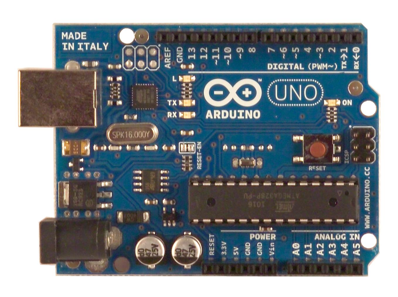
- Let’s now talk about its Parts- 1) Atmega328: The microcontroller is what makes Arduino what it is. It processes data and initiates each command as instructed.
- 2) USB port: It is used when we need to upload the code into the Arduino.
3) DC power port: it is used when the port is already uploaded and we only need to power the Arduino to make it work.
4) Clock Oscillator: Like its name it helps the Arduino to know the time to initiate a command but unlike normal clock oscillators in watches these measure time in milliseconds.
5) Power pins: These pins provide power to the various sensors, components etc. that are connected to the Arduino.
6) Analog pins: Analog data is basically all the values in a particular range. The analog input pins can measure voltage. Digital data is either off or on; analog data encompasses all the values between these two thresholds. Sensors usually output analog readings. The Arduino Uno contains 6 analog pins (A0-A5) in the bottom right corner.
7) Digital pins: These 14 pins, that scale across the top edge, are usually used in sensors only for on or off. Like indicated earlier digital data is just on or off so these pins are used for just turning off or on. Out of these 14 pins 2 (1 and 0) are for receiving and transmitting signals with other Arduino’s and some modules like Bluetooth module. Then 6 other pins namely 3,5,6,9,10,11 are known as PWM pins and have the symbol “~” between them. These pins are basically digital input pins. And all the other remaining pins are digital output pins.
8) Reset button: This button runs the uploaded program again without the need of uploading the program again.
- Now we come to the best part- THE MAKING OF THE CIRCUIT!!!!
So first let’s start with the wiring:
Materials Required: A LED of your favourite colour, Arduino Uno and 2 wires, one Breadboard
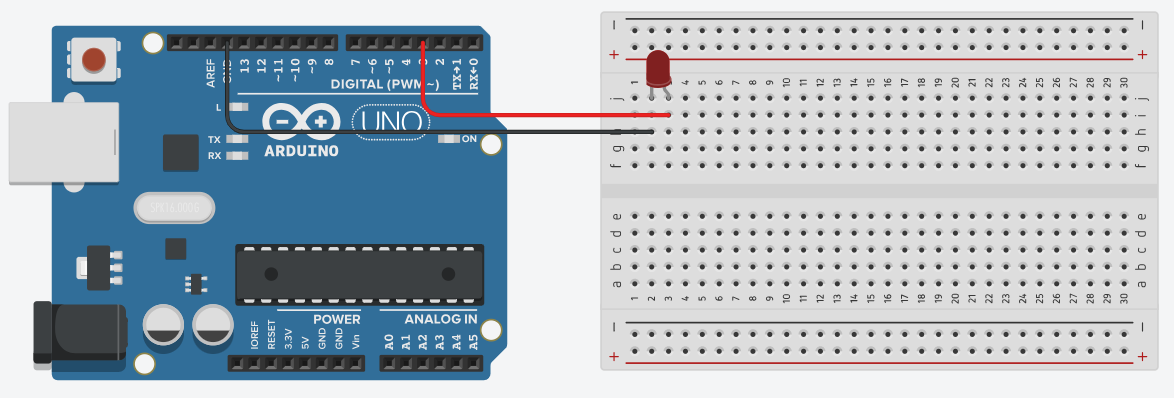
Step 1- fix the LED to the breadboard like in the figure
Step 2- connect one end of a wire to the positive terminal of the battery and the other end to any one of the digital pins (like I have chosen 3).
Step 3- connect the other wire to the negative end of the battery and the other end of the wire to the GND pin on the Arduino.
Your Model should look something like this

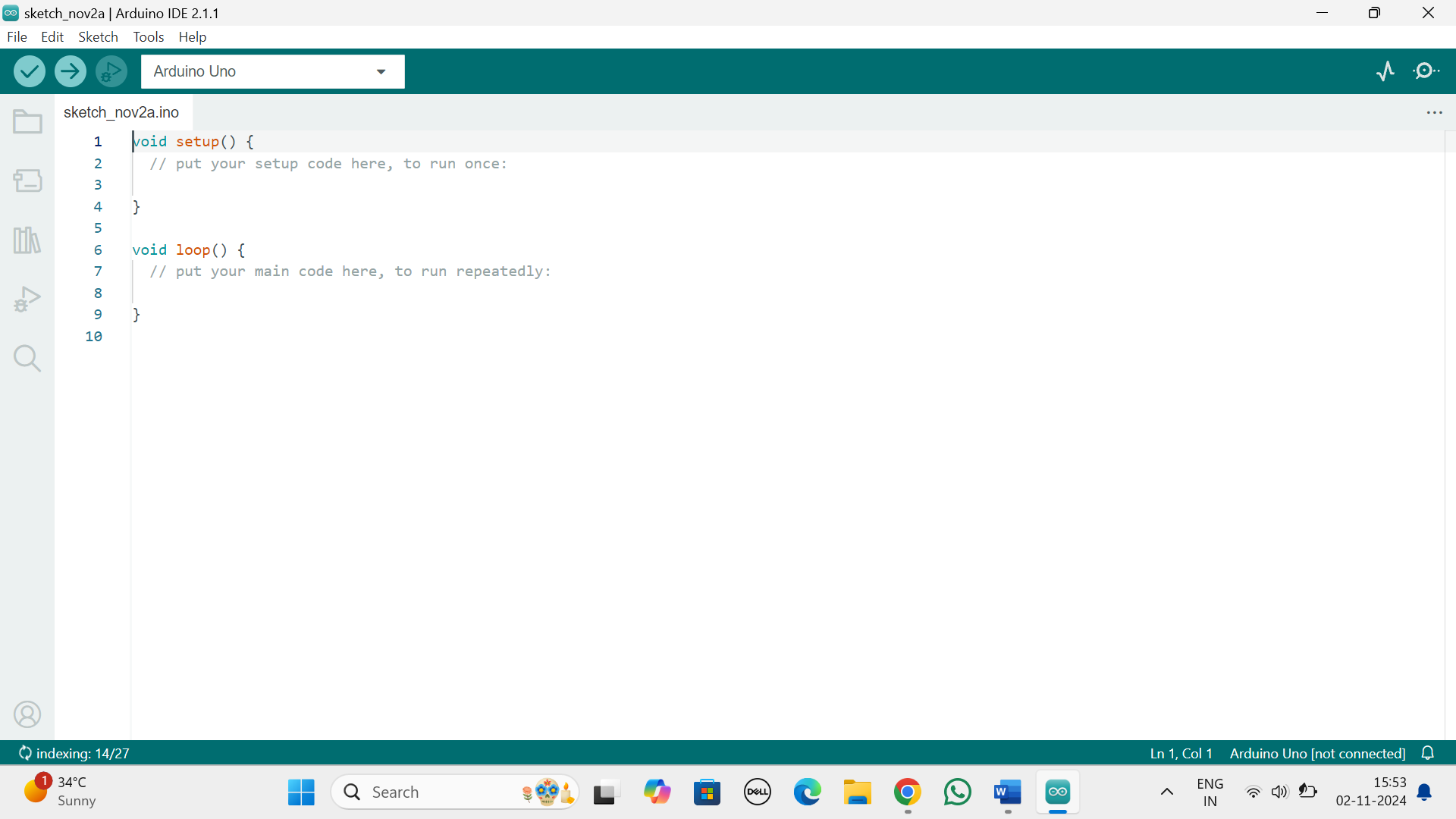
Now the Coding- when you open Arduino IDE, the home screen should look like this—

So, in void setup we will first introduce our element by using its pin as its name and whether it is a output device or input device so we will write –
void setup() {
pinMode(3,OUTPUT);
}
void loop() {
// put your main code here, to run repeatedly:
}
Then in void loop we will put in our main code to blink the LED-
void setup() {
pinMode(3,OUTPUT);
}
void loop() {
digitalWrite(3,HIGH);
delay(1000);
digitalWrite(3,LOW);
delay(1000);
}
If you follow all the step and do the connections just right you will blink the LED.
Now let me explain the code- Here “HIGH” means ON and “LOW” means OFF. And when we add delay we give a specific time limit between the off and on of the LED. So here we have given a delay of 1000 milisecond which is equal to 1 second.
So now you have learnt a bit basic about Arduino and a small code so now you can amaze your friends with it. So until we meet again. BYE.

